Vfd Schematic Diagram
Vfd application working vfds implementation drive frequency variable principle Wiring vfd motor control circuit diagram Vfd diagram plc wiring control circuit schematic drive using ladder diagrams connections logic
Inverter Drive Motor Connection | Home Wiring Diagram
Vfd controlled by switches Vfd wiring diagram control circuit schematic output programming spindle symbols diagrams using cnc board Abb diagram wiring vfd dtc control drive acs800 drives panel acs phase motor manual basic systems schematron detail collection
Vfd piping schematic symbol
Vfd abb ach550 schematic 3phase filbuild induction pls plcVfd circuit diagram schematic wiring motor understanding drive variable frequency components vfds output rectifier fig resolution click Vfd diagramWiring diagram for vfd.
Vfd diagram ac drives wiring operation motor principles circuit variable frequency panel drive schematic dc pulse width inverter phase vsdUnderstanding vfd circuit Abb vfd control wiring diagramBrief explaination about working of vfds, benefits and application.

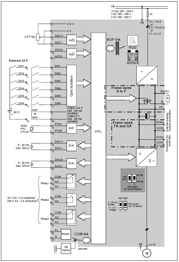
Vfd diagram drive block variable frequency control topics electrical engineering interview
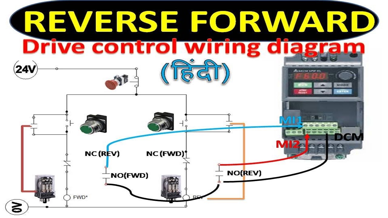
Vfd wiring inverter relay genus controlsVfd variable speed motor drive ac diagram installation block switches controlled control frequency connected function phase drives controller terminals components 101 electrical engineering interview topics: variable frequency driveInverter drive motor connection.
Wiring diagram for vfdVfd wiring powerflex lorestan delta piping hubs plc wrg Principles of operationVfd inverter.
Vfd diagram wiring circuit drive variable frequency types
Vfd diagram variable frequencyWiring diagram for vfd Vfd or inverter drive power component schematic.
.